May 16, 2026
Why It Doesn‘t Crack: Understanding Thermal Shock Resistance
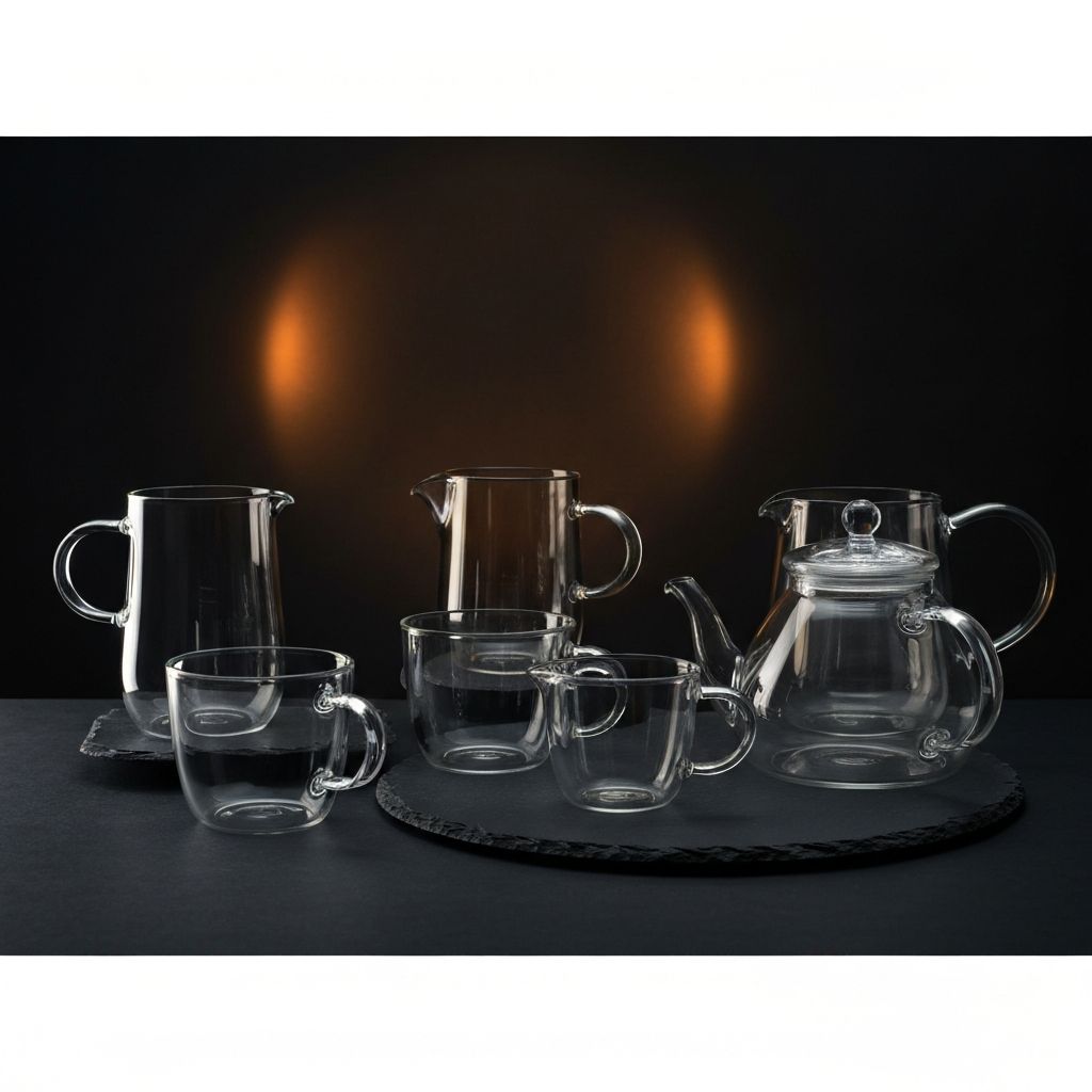
A ceramic crucible pulled straight from a kiln at 1200°C and set onto a stainless steel bench. It doesn’t crack. A thin-walled drinking glass, passed under a cold tap and then filled with hot water, shatters instantly. Same thermal shock principle. Radically different outcomes. Why?
Thermal shock resistance is not about how “strong” a material is. It‘s about how a material handles the stress created by a temperature gradient. When glass is heated locally, the hot zone tries to expand—but it’s rigidly constrained by the surrounding cold material. Internal stress exceeds the glass‘s fracture strength within seconds, and a crack rips from the surface inward. The crucible survives because its material tolerates limited microcrack propagation without full penetration. Stress at the crack tip gets dissipated before it can drive the crack across the entire section.
This is the two-path nature of thermal shock resistance: either stop the stress from building in the first place, or make sure that when it does build, the damage isn’t catastrophic.
Table of Contents
What Thermal Shock Actually Is
Two Resistance Strategies: Crack Initiation vs. Crack Propagation
Who Survives, Who Doesn‘t
Three Parameters That Rule Everything
Quantifying It: From R to R′′′
Design-Level Protection
Summary
What Thermal Shock Actually Is
Thermal shock is not a material being “burned.” It’s a non-uniform temperature field — a thin layer, microns to millimeters deep on the material‘s surface, heats or cools first, expanding or contracting while the interior remains at the original temperature. This time lag is often only seconds or fractions of a second, but that’s enough to generate an enormous mechanical stress differential between the surface and the interior.
The most dangerous location during thermal shock is almost always the surface. The vast majority of thermal shock fractures begin as surface cracks initiated under tensile stress, propagating along grain boundaries or transgranularly inward, then instantaneously penetrating the entire cross-section. The larger the temperature difference, the slower the thermal conduction, and the faster the surface heating rate, the more extreme this dynamic stress gradient becomes.
Two Resistance Strategies: Crack Initiation vs. Crack Propagation
Materials resist thermal shock through two fundamentally different paths. You cannot have both simultaneously.
Path one: resist crack initiation. Fused silica is the classic example. Its coefficient of thermal expansion (CTE) is so low it‘s nearly negligible—about 0.5 × 10⁻⁶/°C. Temperature changes produce almost no volume change, so thermal stress never forms in the first place. Drop a red-hot fused silica block into ice water, and it comes out intact. The trade-off: its fracture toughness is low. If a crack does exist internally, the material fractures at stresses far below theoretical strength. Classic brittle behavior. Perfect, or dead.
Path two: resist crack propagation. Fireclay refractory bricks and some coarse ceramics represent this route. These materials contain a high density of pores and microcracks. During rapid heating or cooling, cracks are repeatedly deflected and branched at these defects, dissipating energy step by step. They’re not crack-free—they’re crack-tolerant. Cracks get “locked” at the microscale, propagating slowly or arresting entirely. The price: high porosity means much lower strength than dense ceramics. Sacrifice strength, gain toughness.
Who Survives, Who Doesn‘t
Fused Silica: CTE ~0.5 × 10⁻⁶/°C, moderate thermal conductivity. Exceptional thermal shock resistance. Lab quartz crucibles, cuvettes, and tube furnace windows rely on it. Crack-initiation-resistance route.
Silicon Carbide: Thermal conductivity extremely high (~120 W/m·K), moderate CTE. The material of choice for industrial kiln furniture and heat exchanger tubes. Heat dissipates so fast that a large temperature gradient never forms, so stress stays low.
Alumina: CTE ~8 × 10⁻⁶/°C, thermal conductivity a few percent of SiC’s. Rapid heating or cooling is its Achilles‘ heel. High strength and hardness make it suitable for steady-state high-temperature environments, not thermal cycling.
Soda-Lime Glass: CTE ~9 × 10⁻⁶/°C, very low thermal conductivity. Local heating drives stress to the fracture limit within seconds. The classic shattered kitchen measuring cup is a textbook thermal shock failure.
Graphite: Thermal conductivity extremely high (~150 W/m·K), low CTE, thermal shock resistance similar to SiC. And uniquely, its strength increases with temperature—remaining stable to 2500°C. The ultimate material for high-temperature furnace heating elements and crucibles.
Three Parameters That Rule Everything
First, the coefficient of thermal expansion (CTE) is the single most powerful lever on thermal shock resistance. The lower the CTE, the smaller the dimensional change with temperature, and the lower the thermal stress. Many material design optimizations are essentially exercises in CTE reduction—such as introducing a secondary phase into alumina to pull the expansion coefficient down.
Second, thermal conductivity determines how large a temperature gradient can build. Higher thermal conductivity means faster heat dissipation, a smaller temperature difference between surface and core, and lower stress. In applications with repeated rapid cooling, thermal conductivity matters even more than CTE.
Third, fracture toughness and elastic modulus together govern how far a crack can run. High fracture toughness means more energy is required for crack propagation. A lower elastic modulus means lower stress for the same strain. These two properties jointly determine whether a material stays crack-free or survives with non-critical cracking. Heterogeneous microstructures—such as layered or fiber-reinforced ceramics—introduce numerous interfaces into the crack path. Each interface acts as an energy absorption zone: cracks bend and branch at interfaces, dissipating energy incrementally and suppressing catastrophic through-fracture.
Quantifying It: From R to R′′′
The thermal shock resistance of ceramic materials is commonly quantified through the Kingery parameters. This is not a single metric but a progressive framework matched to increasingly severe service temperature gradients:
Parameter | Applicable Condition | Core Optimization Direction |
R (First thermal shock factor) | Extremely rapid quench (Biot number → ∞) | Strength / (Elastic modulus × CTE) |
R′ | Moderate cooling rate | Introduces thermal conductivity; favors good conductors |
R′′′ | Slow cooling or steady-state conditions | Introduces Poisson’s ratio; suits energy-release-rate-dominated failure |
These parameters are not ornaments in a handful of theoretical papers—they have been incorporated into white papers and material databases (e.g., CES EduPack) used for industrial ceramic selection. The Biot number compares the material‘s surface-layer thermal conductance against the surface heat transfer intensity: when Biot < 0.2, thermal stress is negligible. When Biot > 10, stress reaches its maximum, and the material with the highest R parameter should be selected. For ceramic components in industrial gas turbines, transient thermal stress analysis frequently calls on R′.
For practical procurement and material comparison: calculating the R parameter requires at minimum knowledge of the material’s fracture strength, elastic modulus, and CTE. If a material supplier, when bidding or submitting samples, can only claim “good thermal shock resistance” but cannot produce calculated R or R′ values or water-quench test results, the thermal shock qualification is not yet complete.
Design-Level Protection
If the material is inherently a brittle ceramic and cannot be changed, geometry and processing become the levers.
Eliminate sharp internal corners. The larger the internal corner radius, the lower the stress concentration. This is the cheapest thermal shock countermeasure available.
Use gradual cross-section transitions. The smoother the transition between thick and thin sections, the smaller the thermal stress differential. Abrupt thickness changes guarantee cracking.
Avoid large, flat, unsupported surfaces. A large flat plane under thermal shock behaves like a drumhead—expansion in the center is constrained by the edges, and tensile stress tears it apart. Ribbing, segmentation, and curvature all reduce constraint stress.
In service, favor heating over cooling. Surface compressive stress is far safer than tensile stress. A cooling trap (surface tensile stress from rapid surface cooling) is an order of magnitude more dangerous than a heating trap (surface compressive stress from rapid surface heating).
Heating rate control is the last line of defense. Reducing the heating rate from over 5°C/s to no more than 2°C/s can lower the peak thermal stress by roughly half or more. For heat treatment of large ceramic components, slow heating or staged ramp-up has been written into relevant EN and ASTM process standards.
Summary
Thermal shock resistance is not a single material property. It is a choice between two strategies: prevent thermal stress from forming—low CTE and high thermal conductivity take this route—or prevent cracks from running through the part—high toughness and microstructural engineering take this route. The ceramic crucible didn‘t crack not because it was “stronger” than the glass, but because it chose the path of sacrificing strength for toughness, dismantling cracks at the microscale. The drinking glass shattered not because it was thin, but because it walked the initiation-controlled path of “perfect or broken,” and that path leaves zero margin for error.
When selecting a material, first determine whether the service condition is thermal-shock-dominated or steady-state-high-temperature-dominated. When thermal shock dominates, look at the R and R′ parameters, and choose fused silica or silicon carbide. When steady-state high temperature dominates, dense alumina and mullite (CTE ~5.3 × 10⁻⁶/°C) can perform well. The most expensive material is not always the best. In thermal shock resistance, the material with the highest R parameter, or the one whose R′ best matches the operating conditions, is often the right answer.